|
The Steering clutch design for the ALLIS
CHALMERS is based on a solid engineering design that was used on several different
clutches in the AC crawler line. You can even see the Allis Chalmers influence and their
steering clutch design showing up as elements in the later Komatsu, Mitsubishi, Furukaw,
Hitachi, and other crawler dozers and crawler loaders. Even Caterpillar used
this design when they engineered the D8 14A and 15A's.
We get a lot of calls and emails from customers all over the world, some of whom are
working on their clutches for the first time, and their questions and concerns involve the
basics of clutch disassembly and assembly. Sending them copies of service manuals is
sometimes helpful but often there is a language barrier so what may seem simple to some is
still a puzzle to others.
In an effort to take some of the mystery out of
the process we've put together a picture album progression of taking the basic steering
clutch apart and putting it back together.
After you look through the process and mentally
digest it a bit, if you need parts for the steering clutch or its components you can click
on the following links to go web pages for your specific machine. We also have these
machines in the yard that we are parting out for additional parts availability.
HD5
AND HD5G'S
HD6
AND HD6G'S
HD9
AND HD9G'S
HD10
HD11
 So that you can
continue on your journey to becoming a Grimy Man (See essay Here) the following primer is
dedicated to you, the Allis Chalmers owner who is doing his best to keep his equipment
going on his own. I hope this helps. So that you can
continue on your journey to becoming a Grimy Man (See essay Here) the following primer is
dedicated to you, the Allis Chalmers owner who is doing his best to keep his equipment
going on his own. I hope this helps.
YOU CAN CLICK ON ALL THE IMAGES
BELOW TO INCREASE THE PICTURE SIZE
 BASIC TOOLS
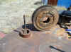
While hydraulic presses, special jigs, and special tools are nice all you really need is a
work surface and some all-thread and you'll be ready to take your steering clutch apart.
For the HD5, HD6, HD9, and HD11's you will also need a 3/4" wrench (or impact
or ratchet equipped with a 3/4" socket) and a pair of wire cutters for the locking
wires. Pay attention to how the lock wires are strung between the adjoining
bolt heads. They are in a figure 8 pattern so that the wires are pulling the heads
in a clockwise manner. There will be additional items needed so read about the
whole process and get all your items scrounged and rounded up. The center post
should be at least 5/8" or 3/4" all-thread. You will also want some
1/2" coarse all-thread or bolts (8 inches long). (To be used as guides later
on)
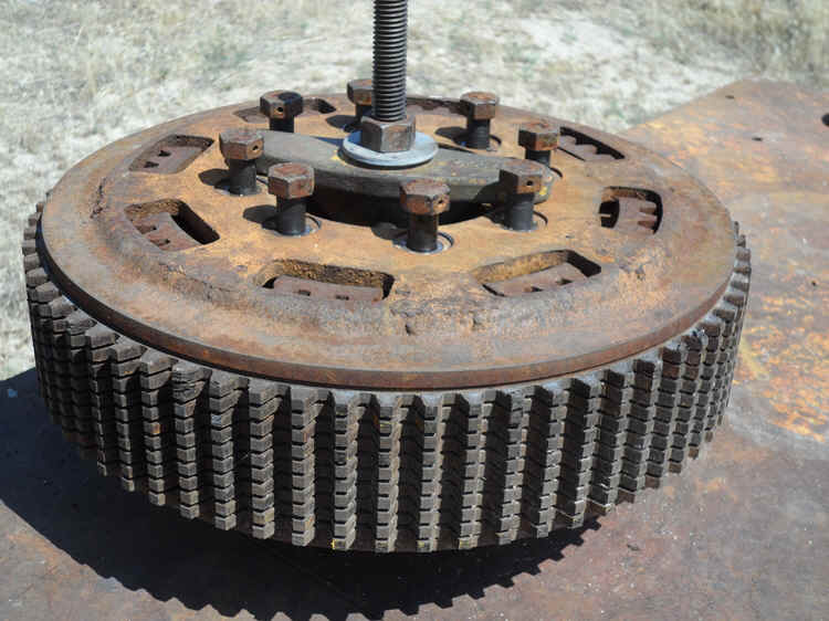
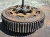
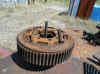
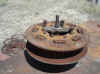
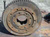 This is the basic clutch we will
be taking apart, This happens to be a clutch removed from either an HD5 or an early
HD6 (Who can tell since they are the same clutch!) The center "donut" is
the compession release plate. When it is pushed in by the throw-out collar This is the basic clutch we will
be taking apart, This happens to be a clutch removed from either an HD5 or an early
HD6 (Who can tell since they are the same clutch!) The center "donut" is
the compession release plate. When it is pushed in by the throw-out collar  the pressure plate on the other side of the clutch is shoved
out and pushed away from the clutch pack so the clutch discs lose their contact with each
other and friction is lost. the pressure plate on the other side of the clutch is shoved
out and pushed away from the clutch pack so the clutch discs lose their contact with each
other and friction is lost.
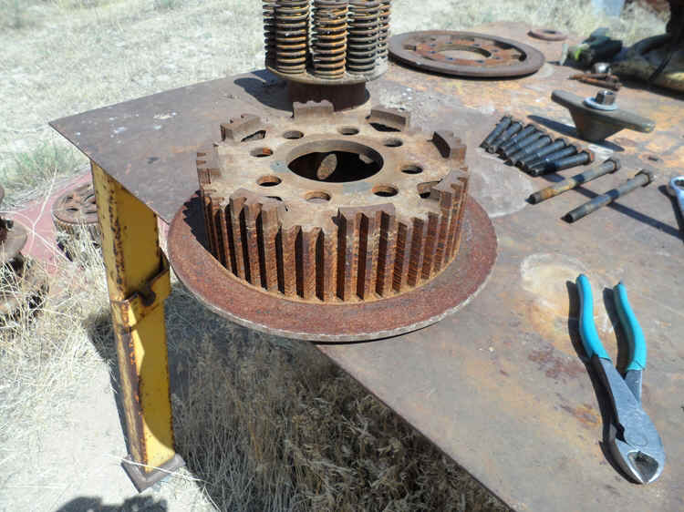
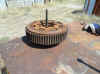
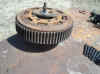
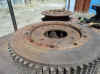
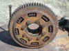 The other side of the steering clutch shows the pressure plate with the
retaining bolts, lock-wires and glimpses of the splined inner driving drum.
The other side of the steering clutch shows the pressure plate with the
retaining bolts, lock-wires and glimpses of the splined inner driving drum.
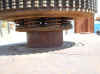
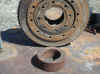 The first thing you will need to
scrounge up will be some kind of spacer to place under the clutch release plate. It
needs to be smaller in diameter than the release plate. You can make a spacer out of
some 2 x 4 scraps. Just be sure that what you make stays within the diameter size of
the clutch release plate.
The first thing you will need to
scrounge up will be some kind of spacer to place under the clutch release plate. It
needs to be smaller in diameter than the release plate. You can make a spacer out of
some 2 x 4 scraps. Just be sure that what you make stays within the diameter size of
the clutch release plate.
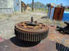
 You are now ready to line things up
and start taking the steering clutch apart. Keep everything centered around the
all-thread post. You are now ready to line things up
and start taking the steering clutch apart. Keep everything centered around the
all-thread post.
 Being centered is important. Being centered is important.
 The second item you will need to scrounge up will
be some kind of cross-piece (T-Bar) to hold the pressure plate in place. We
were lucky to find an old exhaust manifold retainer with tapered ends and the tapered ends
gave us clearance so that our 3/4" socket had clearance to remove all 8 retaining
bolts. These 8 bolts screw into the steering clutch release plate on the other side
of the steering clutch. They are 1/2" bolts 3 1/2" long. (Coarse thread) The second item you will need to scrounge up will
be some kind of cross-piece (T-Bar) to hold the pressure plate in place. We
were lucky to find an old exhaust manifold retainer with tapered ends and the tapered ends
gave us clearance so that our 3/4" socket had clearance to remove all 8 retaining
bolts. These 8 bolts screw into the steering clutch release plate on the other side
of the steering clutch. They are 1/2" bolts 3 1/2" long. (Coarse thread)
Tighten the T-Bar snug to the pressure plate.
It only has to be snug so do
not over tighten. You can break the pressure plate
because everything is solid at this point between the pressure plate clutch release plate.
 Lock wires
can now be removed. Lock wires
can now be removed.
 The qty
(8) 1/2" bolts can be loosened and pulled. The qty
(8) 1/2" bolts can be loosened and pulled.
 Loosen
the T-bolt retaining nut until all pressure from the compression springs is relieved.
You will notice that the clutch is being raised away from the table by the freeing
up of the springs. Loosen
the T-bolt retaining nut until all pressure from the compression springs is relieved.
You will notice that the clutch is being raised away from the table by the freeing
up of the springs.
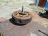
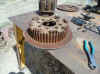
 Compression
spring expansion has raised the clutch and you can now see the exposed clutch release
plate. Previously this plate was recessed inside the clutch by about 1/8". Compression
spring expansion has raised the clutch and you can now see the exposed clutch release
plate. Previously this plate was recessed inside the clutch by about 1/8".
  It
is now time where you can begin to see why you will be using the 1/2" all-thread.
I have shown a couple of bolts in the pictures to show how they will be used as
guides. You can also use bolts if you cut the heads off of them. You can pick
up 1/2" x 8" bolts from your local Lowe's or Home depot for about 2 bucks/bolt.
All-thread can also be used if you don't mind cutting and dressing threads. You can
now totally disassemble the clutch by removing the pressure plate and all of the discs.
You then can lift the inner driving drum off of the spring groups. It
is now time where you can begin to see why you will be using the 1/2" all-thread.
I have shown a couple of bolts in the pictures to show how they will be used as
guides. You can also use bolts if you cut the heads off of them. You can pick
up 1/2" x 8" bolts from your local Lowe's or Home depot for about 2 bucks/bolt.
All-thread can also be used if you don't mind cutting and dressing threads. You can
now totally disassemble the clutch by removing the pressure plate and all of the discs.
You then can lift the inner driving drum off of the spring groups.
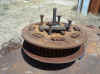
 Springs
are now exposed and can be removed and checked. The springs, when new, are 3.93 to
3.94 in height. We get to cheat a little by just putting a new spring next to the
springs and look for any that are as much as 1/8" lower in height. You can do
basically the same thing by measuring your tallest spring and if it meets spec, line the
others up next to it for comparison. Springs
are now exposed and can be removed and checked. The springs, when new, are 3.93 to
3.94 in height. We get to cheat a little by just putting a new spring next to the
springs and look for any that are as much as 1/8" lower in height. You can do
basically the same thing by measuring your tallest spring and if it meets spec, line the
others up next to it for comparison.
 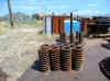 These
springs all measured up so they could be re-used. If your springs suffer from
excessive rust and scaling you may want to consider replacing them anyway or going further
and testing their strength. Behind the springs, in the picture shown, you can see
the bolt spacers. It is these spacers and bolts that create the rigid connection
between the pressure plate and the release plate. These
springs all measured up so they could be re-used. If your springs suffer from
excessive rust and scaling you may want to consider replacing them anyway or going further
and testing their strength. Behind the springs, in the picture shown, you can see
the bolt spacers. It is these spacers and bolts that create the rigid connection
between the pressure plate and the release plate.
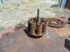
 This
picture may be a little misleading as bolts are shown that do not have their heads
removed. They act as guides to keep the spacers and springs lined up.
Without these guides the spacers can shift during assembly and keep you from
installing the retaining bolts. I've done this so many times that I can get away
with some short cuts but for first timers, I highly recommend using the guide studs.
So now it is time to install your T-Bar and begin compressing the springs. This
picture may be a little misleading as bolts are shown that do not have their heads
removed. They act as guides to keep the spacers and springs lined up.
Without these guides the spacers can shift during assembly and keep you from
installing the retaining bolts. I've done this so many times that I can get away
with some short cuts but for first timers, I highly recommend using the guide studs.
So now it is time to install your T-Bar and begin compressing the springs.
 As
the springs are being compressed you can remove a couple of the guide studs and insert
retaining bolts. They will be floating until they make contact with the thread
bosses on the clutch release plate. As you continue to compress the springs
with the T-Bar you will see a gap being created between the heads of the bolts and the
pressure plate. You can now begin to screw by hand the bolts into the clutch
release plate. Begin replacing the remaining studs with retaining bolts and tighten
them until you bottom them out against the bolt spacers. Now you can remove the
T-bar and your clutch is assembled. (Yes, the pictures shown do not include the
clutch discs. For this tutorial I am trying to show a simple disassembly and
assembly procedure and instill the basic concept that the clutch release plate connected
to the pressure plate by retaining bolts and spacers acts as a solid unit.) As
the springs are being compressed you can remove a couple of the guide studs and insert
retaining bolts. They will be floating until they make contact with the thread
bosses on the clutch release plate. As you continue to compress the springs
with the T-Bar you will see a gap being created between the heads of the bolts and the
pressure plate. You can now begin to screw by hand the bolts into the clutch
release plate. Begin replacing the remaining studs with retaining bolts and tighten
them until you bottom them out against the bolt spacers. Now you can remove the
T-bar and your clutch is assembled. (Yes, the pictures shown do not include the
clutch discs. For this tutorial I am trying to show a simple disassembly and
assembly procedure and instill the basic concept that the clutch release plate connected
to the pressure plate by retaining bolts and spacers acts as a solid unit.)
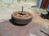
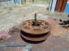  The
final picture shows the assembled clutch and the recessed clutch release plate in relation
to the inner driving drum. It is this difference in height that provides the
important measurement that will tell you if you have a clutch that will work. This
distance, or depth, should be 3/16" of an inch (plus or minus 1/16") If
the distance is greater than 3/16" inch then remove a steel disc. If the clutch
release plate is not recessed then your stack height is too low and you will need to add
discs. Quoting from the service manual below: The
final picture shows the assembled clutch and the recessed clutch release plate in relation
to the inner driving drum. It is this difference in height that provides the
important measurement that will tell you if you have a clutch that will work. This
distance, or depth, should be 3/16" of an inch (plus or minus 1/16") If
the distance is greater than 3/16" inch then remove a steel disc. If the clutch
release plate is not recessed then your stack height is too low and you will need to add
discs. Quoting from the service manual below:
if clutch was assembled correctly and stack height is
within specifications, and pressure plate and hub friction surfaces, seem OK to use, ADD
one steel plate next to pressure plate and re-assemble. If measured distance
(stand-in) is more than specified maximum distance, remove one steel plate from next
to pressure plate (at least one steel plate must be used next to pressure plate) .
I'll put together some future pix showing
you how to assemble the discs both with a brake drum and without the use of a brake drum.
It is almost intuitive and you can probably figure it out but it may still be
helpful to see it done. (remember..........Keep everything centered!!)
The latest service manual covering the
HD5-HD6-HD9-HD11 steering can be seen and downloaded by clicking the link (HERE)
Earlier parts and service manuals can be retrieved below. Reviewing the
different types of literature may be helpful as there are points and examples in one that
may not be in the other.
HD5 STEERING CLUTCH PARTS
HD5 BRAKE PARTS
HD5 STEERING CLUTCH
SERVICE
HD6 STEERING CLUTCH
PARTS
HD6 STEERING CLUTCH
SERVICE
HD9 STEERING CLUTCH PARTS
HD9 STEERING CLUTCH
SERVICE
HD11 STEERING CLUTCH
PARTS
HD11 STEERING CLUTCH
REMOVAL
HD11
STEERING CLUTCH MAINENANCE
Click HERE to view all of our new steering clutch
discs.
|


 So that you can
continue on your journey to becoming a Grimy Man (See essay Here) the following primer is
dedicated to you, the Allis Chalmers owner who is doing his best to keep his equipment
going on his own. I hope this helps.
So that you can
continue on your journey to becoming a Grimy Man (See essay Here) the following primer is
dedicated to you, the Allis Chalmers owner who is doing his best to keep his equipment
going on his own. I hope this helps.